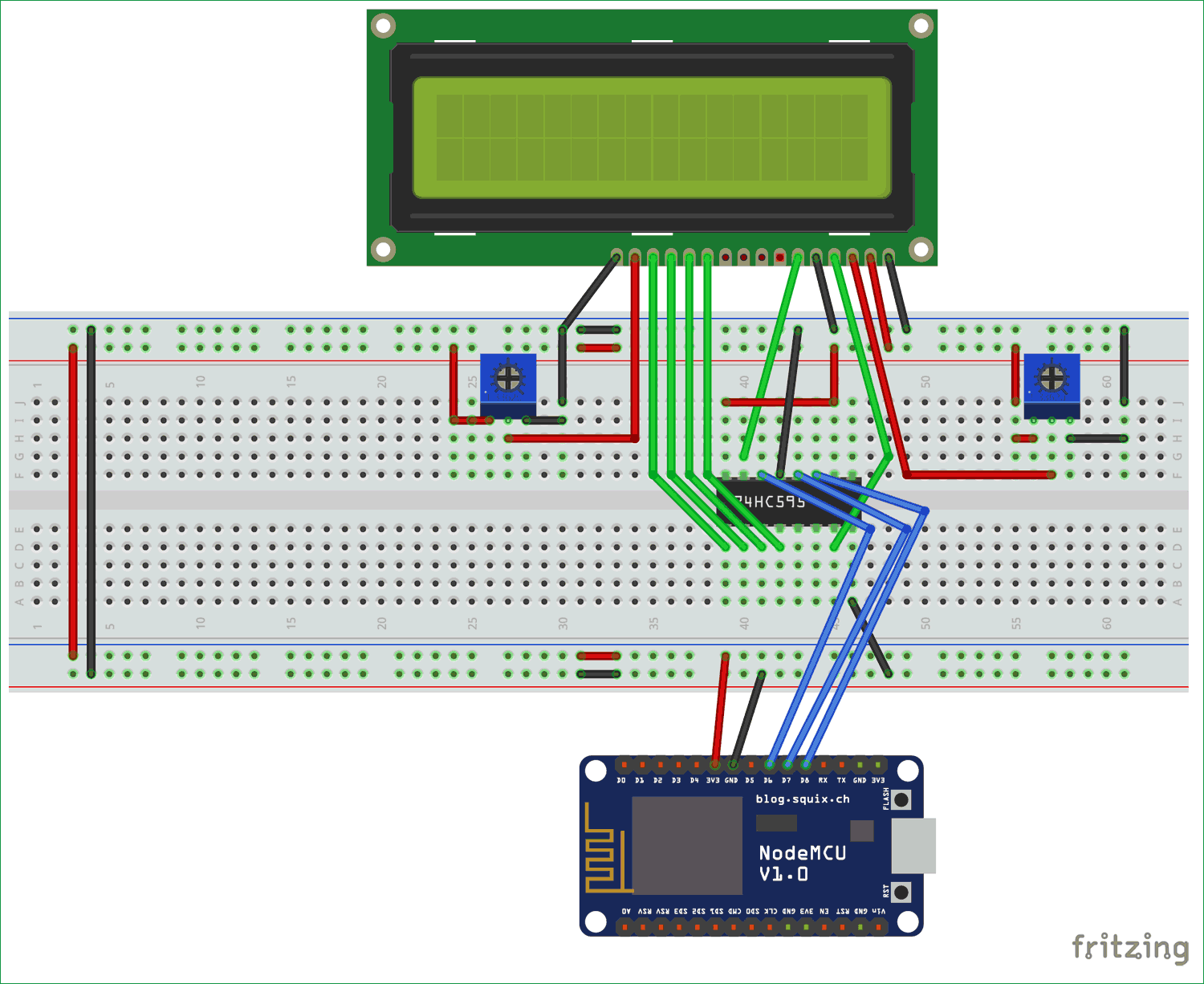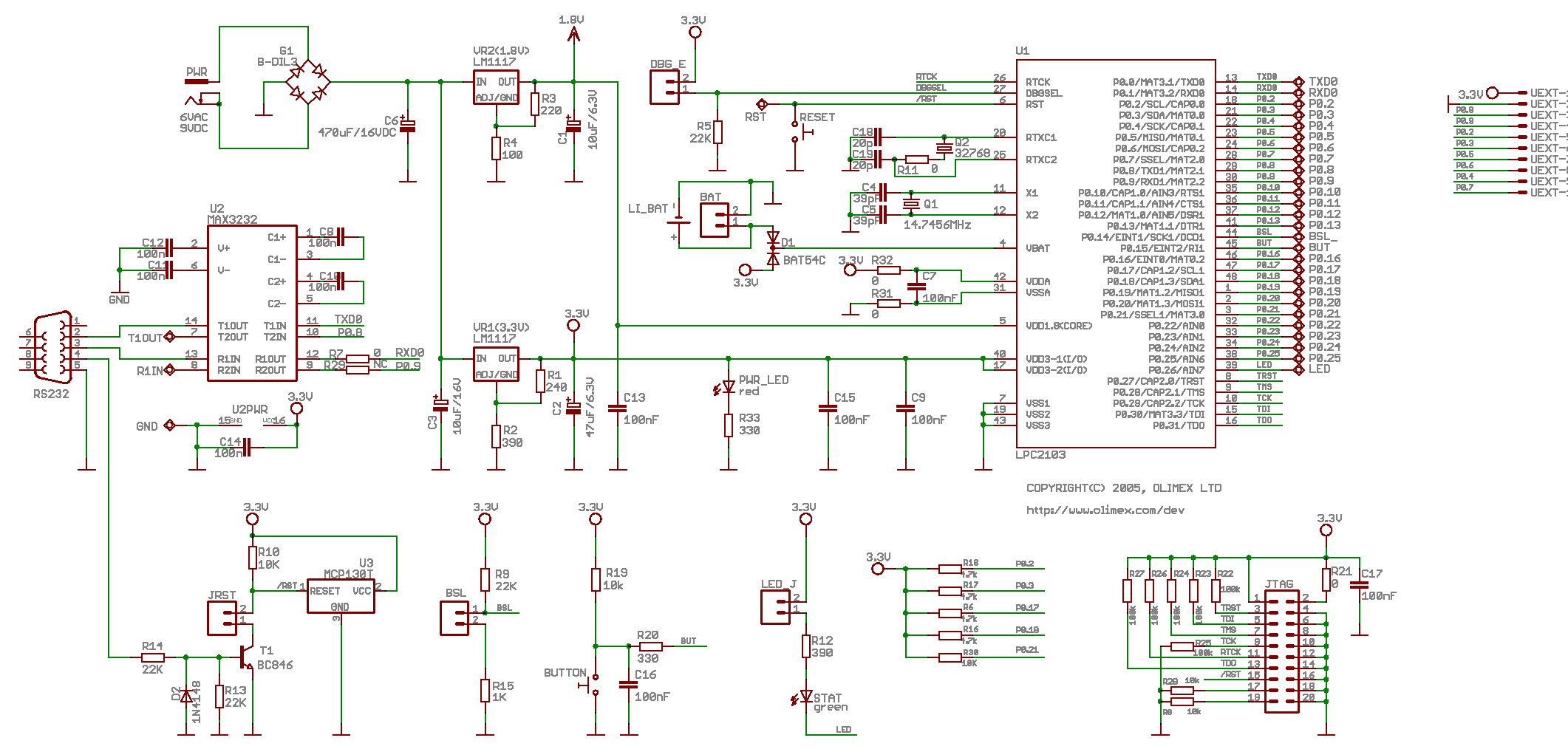

I will show you how to assign pins for LCD in the next section. To do this, we need to change the pin assignment inside the code. In this circuit, we used the PORTB of PIC18F4550.

Make the connections of 16X2 LCD with PIC18F4550 microcontroller according to this circuit diagram. Once we have successfully configured LCD, we can transmit data to LCD.After that send configuration commands to select mode and other configuration settings.Define PIC18F4450 pin that we want to use for sending commands and data to LCD.This contrast register makes adjust to the voltage applied on the VEE pin. Therefore, if you are not able to see anything on LCD after programming, the maximum changes are that you need to adjust contrast with the variable resistor. However, it doesn’t make any major difference.Ī variable resistor is used to adjust the contrast of 5×8 dot pixels according to background light. The only difference between 4-bit and 8-bit is that data transfer speed is faster for 8-bit mode. Therefore, it is recommended to use 4-bit mode interfacing. On the other hand, if we use 4-bit mode, we need only 6 GPIO pins.

So It is recommended to use LCD in four bits mode to save pins of the microcontroller for other applications.Īs you can see in this diagram, if we use 8-bit mode interfacing, we will need to use 11 pins of pic microcontroller. In this tutorial, we have used the 4-bit mode which uses only 4 data lines, thus saving pins of the microcontroller. It can work in two modes, 4-bit and 8-bit. How to interface/Connect LCD with PIC Microcontroller


 0 kommentar(er)
